Mechanics of Materials, 10th Edition Solution Manual
Solve your textbook questions faster and more accurately with Mechanics of Materials, 10th Edition Solution Manual, a reliable guide for every chapter.
Finn Hill
Contributor
4.2
35
4 months ago
Preview (16 of 1569)
Sign in to access the full document!
Solution
1
1–1.
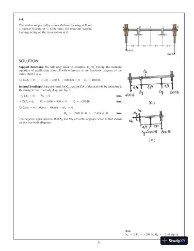
The shaft is supported by a smooth thrust bearing at B and
a journal bearing at C. Determine the resultant internal
loadings acting on the cross section at E.
A E DB C
4 ft
400 lb
800 lb
4 ft 4 ft 4 ft
Solution
Support Reactions: We will only need to compute Cy by writing the moment
equation of equilibrium about B with reference to the free-body diagram of the
entire shaft, Fig. a.
a+ ΣMB = 0; C y(8) + 400(4) - 800(12) = 0 C y = 1000 lb
Internal Loadings: Using the result for Cy, section DE of the shaft will be considered.
Referring to the free-body diagram, Fig. b,
S+ ΣFx = 0; NE = 0 Ans.
+ c ΣFy = 0; VE + 1000 - 800 = 0 VE = -200 lb Ans.
a+ ΣME = 0; 1000(4) - 800(8) - ME = 0
ME = - 2400 lb # ft = - 2.40 kip # ft Ans.
The negative signs indicates that VE and ME act in the opposite sense to that shown
on the free-body diagram.
Ans:
NE = 0, VE = -200 lb, ME = - 2.40 kip # ft
Solution
2
1–2.
Determine the resultant internal normal and shear force in
the member at (a) section a–a and (b) section b–b, each of
which passes through the centroid A. The 500-lb load is
applied along the centroidal axis of the member.
30°
A
ba
b a
500 lb500 lb
Solution
(a)
+S ΣFx = 0; Na - 500 = 0
Na = 500 lb Ans.
+ T ΣFy = 0; Va = 0 Ans.
(b)
R+ ΣFx = 0; Nb - 500 cos 30° = 0
Nb = 433 lb Ans.
+Q ΣFy = 0; Vb - 500 sin 30° = 0
Vb = 250 lb Ans.
Ans:
(a) Na = 500 lb, Va = 0,
(b) Nb = 433 lb, Vb = 250 lb
Loading page 6...
Loading page 7...
Loading page 8...
Loading page 9...
Loading page 10...
Loading page 11...
Loading page 12...
Loading page 13...
Loading page 14...
Loading page 15...
Loading page 16...
13 more pages available. Scroll down to load them.
Preview Mode
Sign in to access the full document!
100%
Study Now!
XY-Copilot AI
Unlimited Access
Secure Payment
Instant Access
24/7 Support
Document Chat
Document Details
Subject
Mechanical Engineering