Solution Manual For Materials For Civil And Construction Engineers, 3rd Edition

Solution Manual For Materials For Civil And Construction Engineers, 3rd Edition makes textbook problem-solving easy with a comprehensive guide that explains every step.

Henry Martinez
Contributor
4.4
51
5 months ago
Preview (16 of 105 Pages)
100%
Purchase to unlock

Page 1

Solution Manual For Materials For Civil And Construction Engineers, 3rd Edition - Page 1 preview image

Loading page image...

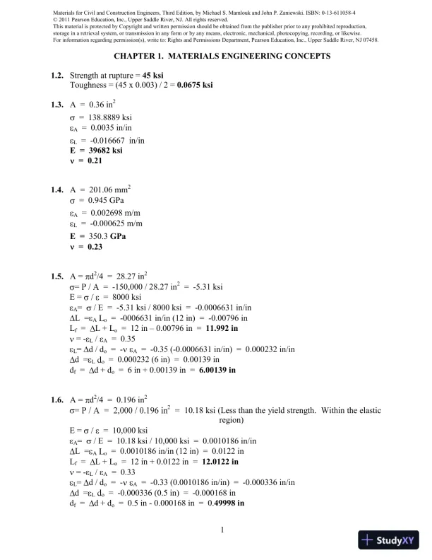
1CHAPTER 1. MATERIALS ENGINEERING CONCEPTS1.2.Strength at rupture =45 ksiToughness = (45 x 0.003) / 2 =0.0675 ksi1.3.A = 0.36 in2= 138.8889 ksiA= 0.0035 in/inL= -0.016667 in/inE = 39682 ksi= 0.211.4.A = 201.06 mm2= 0.945 GPaA= 0.002698 m/mL= -0.000625 m/mE =350.3GPa= 0.231.5.A =d2/4 = 28.27 in2-150,000 / 28.27 in2= -5.31 ksiE == 8000 ksiA/ E = -5.31 ksi / 8000 ksi = -0.0006631 in/inL =Ao= -0006631 in/in (12 in) = -0.00796 inLf=L + Lo= 12 in0.00796 in =11.992 in= -L/A= 0.35Ld / do= -A= -0.35 (-0.0006631 in/in) = 0.000232 in/ind =Lo= 0.000232 (6 in) = 0.00139 indf=d + do= 6 in + 0.00139 in =6.00139 in1.6.A =d2/4 = 0.196 in22= 10.18 ksi (Less than the yield strength. Within the elasticregion)E == 10,000 ksiA/ E = 10.18 ksi / 10,000 ksi = 0.0010186 in/inL =Ao= 0.0010186 in/in (12 in) = 0.0122 inLf=L + Lo= 12 in + 0.0122 in =12.0122 in= -L/A= 0.33Ld / do= -A= -0.33 (0.0010186 in/in) = -0.000336 in/ind =Lo= -0.000336 (0.5 in) = -0.000168 indf=d + do= 0.5 in - 0.000168 in = 0.49998 in12 in6 in12 in6 in

Page 2

Solution Manual For Materials For Civil And Construction Engineers, 3rd Edition - Page 2 preview image

Loading page image...

Page 3

Solution Manual For Materials For Civil And Construction Engineers, 3rd Edition - Page 3 preview image

Loading page image...

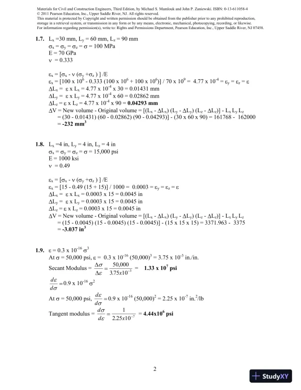
21.7.Lx=30 mm, Ly= 60 mm, Lz= 90 mmx=y=z== 100 MPaE = 70 GPa= 0.333x= [x-(y+z) ] /Ex=[100 x 106-0.333 (100 x 106+ 100 x 106)] / 70 x 109= 4.77 x 10-4=y=z=Lx=x Lx= 4.77 x 10-4x 30 = 0.01431 mmLy=x Ly= 4.77 x 10-4x 60 = 0.02862 mmLz=x Lz= 4.77 x 10-4x 90 =0.04293 mmV = New volume - Original volume = [(Lx-Lx) (Ly-Ly) (Lz-Lz)] - LxLyLz= (30 - 0.01431) (60 - 0.02862) (90 - 0.04293)] - (30 x 60 x 90) = 161768 - 162000=-232 mm31.8.Lx=4 in, Ly= 4 in, Lz= 4 inx=y=z== 15,000 psiE = 1000 ksi= 0.49x= [x-(y+z) ] /Ex= [15 - 0.49 (15 + 15)] / 1000 = 0.0003 =y=z=Lx=x Lx= 0.0003 x 15 = 0.0045 inLy=x Ly= 0.0003 x 15 = 0.0045 inLz=x Lz= 0.0003 x 15 = 0.0045 inV = New volume - Original volume = [(Lx-Lx) (Ly-Ly) (Lz-Lz)] - LxLyLz= (15 - 0.0045) (15 - 0.0045) (15 - 0.0045)] - (15 x 15 x 15) = 3371.963 - 3375=-3.037 in31.9.= 0.3 x 10-163At= 50,000 psi,= 0.3 x 10⁻¹⁶(50,000)3= 3.75 x 10⁻³in./in.Secant Modulus =50 0003 75 103,.x=1.33 x 10⁷psidd0.9 x 10-162At= 50,000 psi,dd0.9 x 10-16(50,000)2= 2.25 x 10⁻⁷in.2/lbTangent modulus =ddx12 25 107.=4.44x10⁶psi

Page 4

Solution Manual For Materials For Civil And Construction Engineers, 3rd Edition - Page 4 preview image

Loading page image...

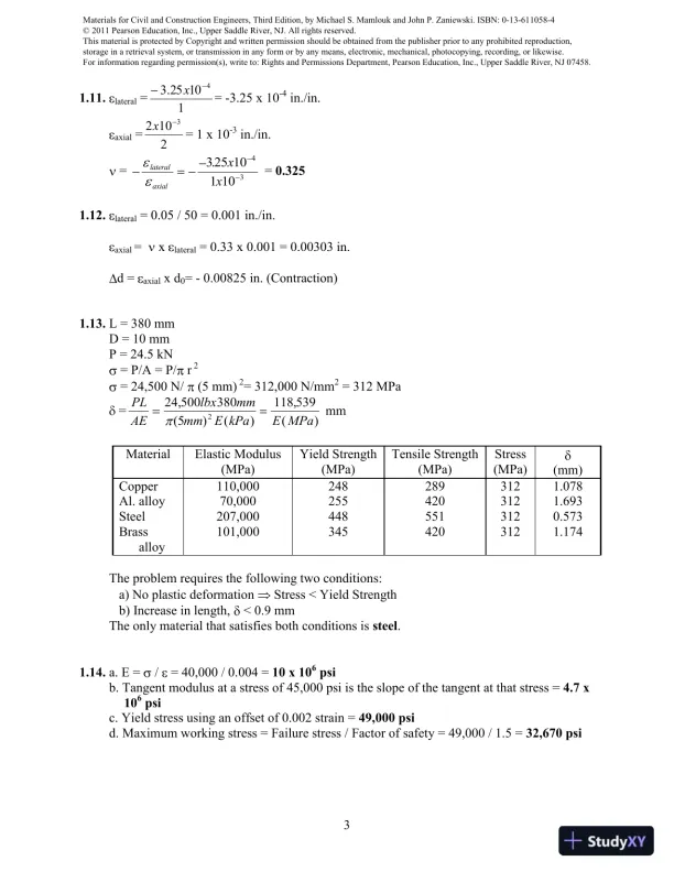
31.11.lateral=11025.34x= -3.25 x 10⁻⁴in./in.axial=2 1023x= 1 x 10⁻³in./in.=lateralaxialxx325 101 1043.=0.3251.12.lateral= 0.05 / 50 = 0.001 in./in.axial=xlateral= 0.33 x 0.001 = 0.00303 in.d =axialx d0= - 0.00825 in. (Contraction)1.13.L = 380 mmD = 10 mmP = 24.5 kN= P/A = P/r2= 24,500 N/(5 mm)2= 312,000 N/mm2= 312 MPa=PLAElbxmmmmE kPaE MPa24 500380118 5392,(5)(),()mmMaterialElasticModulus(MPa)Yield Strength(MPa)Tensile Strength(MPa)Stress(MPa)(mm)Copper110,0002482893121.078Al. alloy70,0002554203121.693Steel207,0004485513120.573Brassalloy101,0003454203121.174The problem requires the following two conditions:a) No plastic deformationStress < Yield Strengthb) Increase in length,< 0.9 mmThe only material that satisfies both conditions issteel.1.14.a. E =/= 40,000 / 0.004 =10 x 106psib. Tangent modulus at a stress of 45,000 psi is the slope of the tangent at that stress =4.7 x10⁶psic. Yield stress using an offset of 0.002 strain =49,000 psid. Maximum working stress = Failure stress / Factor of safety = 49,000 / 1.5 =32,670 psi

Page 5

Solution Manual For Materials For Civil And Construction Engineers, 3rd Edition - Page 5 preview image

Loading page image...

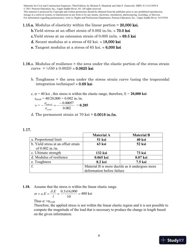
41.15.a. Modulus of elasticity within the linear portion = 20,000 ksi.b.Yield stress at an offset strain of 0.002 in./in.70.0 ksic.Yield stress at an extension strain of 0.005 in/in.69.5 ksid. Secant modulus at a stress of 62 ksi.18,000 ksie. Tangent modulus at a stress of 65 ksi.6,000 ksi1.16.a. Modulus of resilience = the area under the elastic portion of the stress straincurve = ½(50 x 0.0025)0.0625 ksib. Toughness = the area under the stress strain curve (using the trapezoidalintegration technique)0.69 ksic= 40 ksi , this stress is within the elastic range, therefore, E =20,000 ksiaxial= 40/20,000 = 0.002 in./in.=002.000057.0axiallateral=0.285d. The permanent strain at 70 ksi = 0.0018 in./in.1.17.Material AMaterial Ba. Proportional limit51 ksi40 ksib. Yield stress at an offset strainof 0.002 in./in.63 ksi52 ksic. Ultimate strength132 ksi73 ksid. Modulus of resilience0.065 ksi0.07 ksie. Toughness8.2 ksi7.5 ksif.Material B is more ductile as it undergoes moredeformation before failure1.18.Assume that the stress is within the linear elastic range.10000,163.0..xlEE480 ksiThus>yieldTherefore, the applied stress is not within the linear elastic region and it is not possible tocompute the magnitude of theload that is necessary to produce the change in lengthbasedon the given information.

Page 6

Solution Manual For Materials For Civil And Construction Engineers, 3rd Edition - Page 6 preview image

Loading page image...

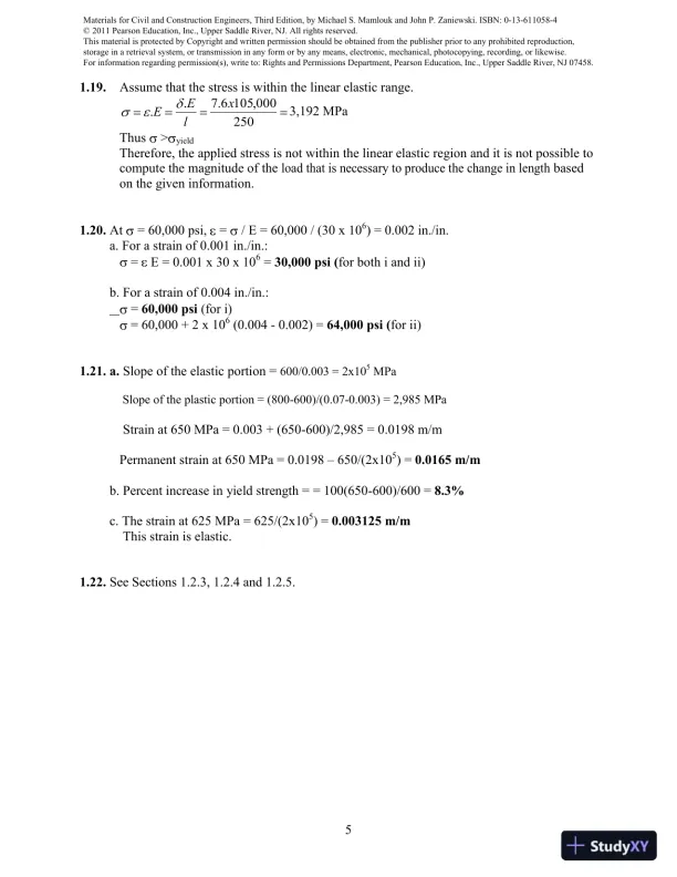
51.19.Assume that the stress is within the linear elastic range.250000,1056.7..xlEE3,192 MPaThus>yieldTherefore, the applied stress is not within the linear elastic region and it is not possible tocompute the magnitude of theload that is necessary to produce the change in lengthbasedon the given information.1.20.At= 60,000 psi,=/ E = 60,000 / (30 x 106) = 0.002 in./in.a. For a strain of 0.001 in./in.:=E = 0.001 x 30 x 106=30,000 psi (for both i and ii)b. For a strain of 0.004 in./in.:=60,000 psi(for i)= 60,000 + 2 x 10⁶(0.004 - 0.002) =64,000 psi (for ii)1.21. a.Slope of the elastic portion =600/0.003 = 2x10⁵MPaSlope of the plastic portion = (800-600)/(0.07-0.003) = 2,985 MPaStrain at 650 MPa = 0.003 + (650-600)/2,985 = 0.0198 m/mPermanent strain at 650 MPa = 0.0198650/(2x105) =0.0165 m/mb. Percent increase in yield strength = = 100(650-600)/600 =8.3%c. The strain at 625 MPa = 625/(2x105) =0.003125 m/mThis strain is elastic.1.22.See Sections 1.2.3, 1.2.4 and 1.2.5.

Page 7

Solution Manual For Materials For Civil And Construction Engineers, 3rd Edition - Page 7 preview image

Loading page image...

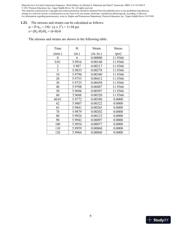
61.23.The stresses and strains can be calculated as follows:= P/Ao= 150 / (x 22) = 11.94 psi= (Ho-H)/Ho= (6-H)/6The stresses and strains are shown in the following table:Time(min.)H(in.)Strain(in./in.)Stress(psi)060.0000011.93660.015.99160.0014011.936625.9870.0021711.936655.98330.0027811.9366105.97960.0034011.9366205.97530.0041211.9366305.97250.0045811.9366405.97080.0048711.9366505.96960.0050711.9366605.96880.0052011.936660.015.97720.003800.0000625.98070.003220.0000655.98410.002650.0000705.98790.002020.0000805.99260.001230.0000905.99420.000970.00001005.99540.000770.00001105.99590.000680.00001205.99640.000600.0000

Page 8

Solution Manual For Materials For Civil And Construction Engineers, 3rd Edition - Page 8 preview image

Loading page image...

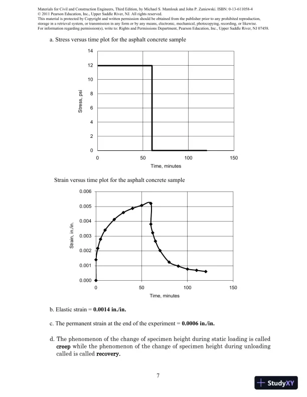
7a. Stress versus time plot for the asphalt concrete sampleStrain versus time plot for the asphalt concrete sampleb. Elastic strain =0.0014 in./in.c. The permanent strain at the end of the experiment =0.0006 in./in.d.The phenomenon of the change of specimen height during static loading is calledcreepwhile the phenomenon of the change of specimen height during unloadingcalled is calledrecovery.02468101214050100150Stress, psiTime, minutes0.0000.0010.0020.0030.0040.0050.006050100150Strain, in./in.Time, minutes

Page 9

Solution Manual For Materials For Civil And Construction Engineers, 3rd Edition - Page 9 preview image

Loading page image...

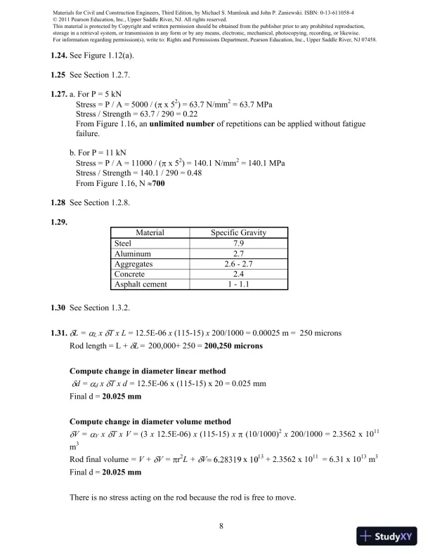
81.24.See Figure 1.12(a).1.25See Section 1.2.7.1.27.a. For P = 5 kNStress = P / A = 5000 / (x 52) = 63.7 N/mm2= 63.7 MPaStress / Strength = 63.7 / 290 = 0.22From Figure 1.16, anunlimited numberof repetitions can be applied without fatiguefailure.b. For P = 11 kNStress = P / A = 11000 / (x 52) = 140.1 N/mm2= 140.1 MPaStress / Strength = 140.1 / 290 = 0.48From Figure 1.16, N7001.28See Section 1.2.8.1.29.MaterialSpecific GravitySteel7.9Aluminum2.7Aggregates2.6-2.7Concrete2.4Asphalt cement1-1.11.30See Section 1.3.2.1.31.L =LxT x L= 12.5E-06x(115-15)x200/1000= 0.00025 m = 250 micronsRod length = L +L=200,000+ 250 =200,250 micronsCompute change in diameter linear methodd =dxT x d =12.5E-06 x (115-15) x 20 = 0.025 mmFinal d =20.025 mmCompute change in diameter volume methodV =VxT x V= (3x12.5E-06)x(115-15)x(10/1000)2x200/1000 = 2.3562 x 10¹¹m3Rod final volume= V +V=r2L +Vx+2.3562 x 1011=6.31 x 10¹³m3Final d =20.025 mmThere is no stress acting on the rod because the rod is free to move.

Page 10

Solution Manual For Materials For Civil And Construction Engineers, 3rd Edition - Page 10 preview image

Loading page image...

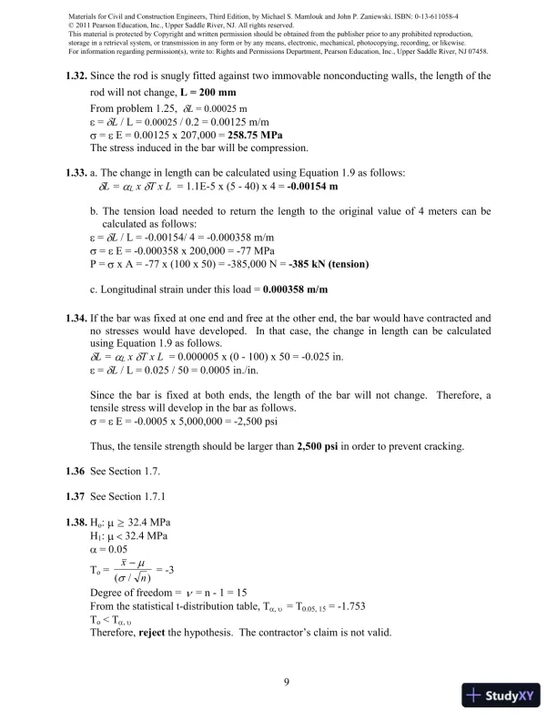
91.32.Since the rod is snugly fitted against two immovable nonconducting walls, the length of therod will not change,L = 200 mmFrom problem 1.25,L= 0.00025 m=L/ L =0.00025/ 0.2 = 0.00125 m/m=E = 0.00125 x 207,000 =258.75 MPaThe stress induced in the bar will be compression.1.33.a. The change in length can be calculated using Equation 1.9 as follows:L =LxT x L= 1.1E-5 x (5 - 40) x 4=-0.00154 mb. The tension load needed to return the length to the original value of 4 meters can becalculated as follows:=L/ L = -0.00154/ 4 = -0.000358 m/m=E = -0.000358 x 200,000 = -77 MPaP =x A = -77 x (100 x 50) = -385,000 N =-385 kN (tension)c. Longitudinal strain under this load =0.000358 m/m1.34.If the bar was fixed at one end and free at the other end, the bar would have contracted andno stresses would have developed.In that case, the change in length can be calculatedusing Equation 1.9 as follows.L =LxT x L= 0.000005 x (0 - 100) x 50= -0.025 in.=L/ L = 0.025 / 50 = 0.0005 in./in.Since the bar is fixed at both ends, the length of the bar will not change.Therefore, atensile stress will develop in the bar as follows.=E = -0.0005 x 5,000,000 = -2,500 psiThus, the tensile strength should be larger than2,500 psiin order to prevent cracking.1.36See Section 1.7.1.37See Section 1.7.11.38.Ho:32.4 MPaH1:32.4 MPa= 0.05To=xn(/)= -3Degree of freedom == n - 1 = 15From the statistical t-distribution table, T,= T0.05, 15= -1.753To< T,Therefore,rejectthe hypothesis. The contractor’s claim is not valid.

Page 11

Solution Manual For Materials For Civil And Construction Engineers, 3rd Edition - Page 11 preview image

Loading page image...

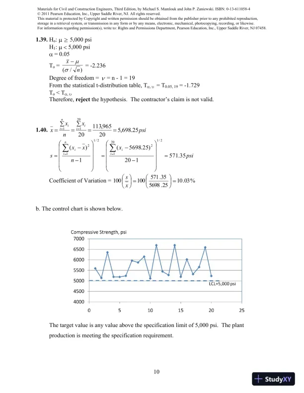
101.39.Ho:5,000 psiH1:5,000 psi= 0.05To=xn(/)= -2.236Degree of freedom == n - 1 = 19From the statistical t-distribution table, T,= T0.05, 19= -1.729To< T,Therefore,rejectthe hypothesis. The contractor’s claim is not valid.1.40.psixnxxiinii25.698,520965,113202011psixnxxsiinii35.571120)25.5698(1)(2/120122/112Coefficient of Variation =%03.1025.569835.571100100xsb. The control chart is shown below.The target value is any value above the specification limit of 5,000 psi. The plantproduction is meeting the specification requirement.

Page 12

Solution Manual For Materials For Civil And Construction Engineers, 3rd Edition - Page 12 preview image

Loading page image...

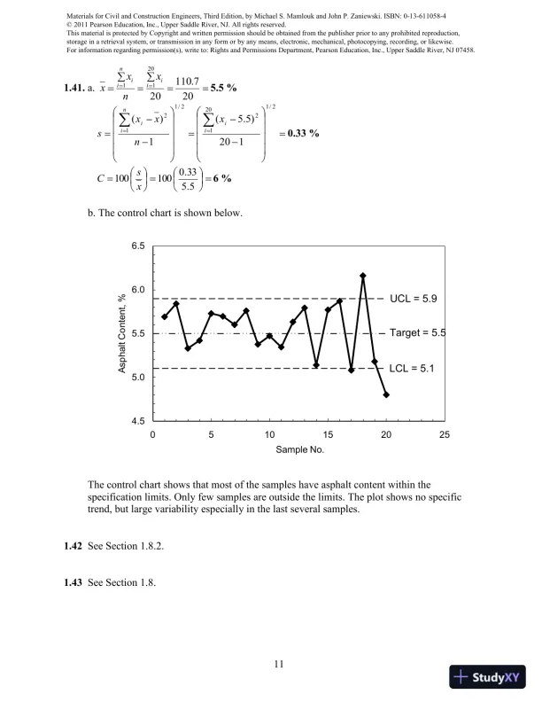
111.41.a.207.110202011iiniixnxx5.5 %2/120122/112120)5.5(1)(iiniixnxxs0.33 %5.533.0100100xsC6 %b. The control chart is shown below.The control chart shows that most of the samples have asphalt content within thespecification limits. Only few samples are outside the limits. The plot shows no specifictrend, but large variability especially in the last several samples.1.42See Section 1.8.2.1.43See Section 1.8.4.55.05.56.06.50510152025Asphalt Content, %Sample No.UCL = 5.9LCL = 5.1Target = 5.5

Page 13

Solution Manual For Materials For Civil And Construction Engineers, 3rd Edition - Page 13 preview image

Loading page image...

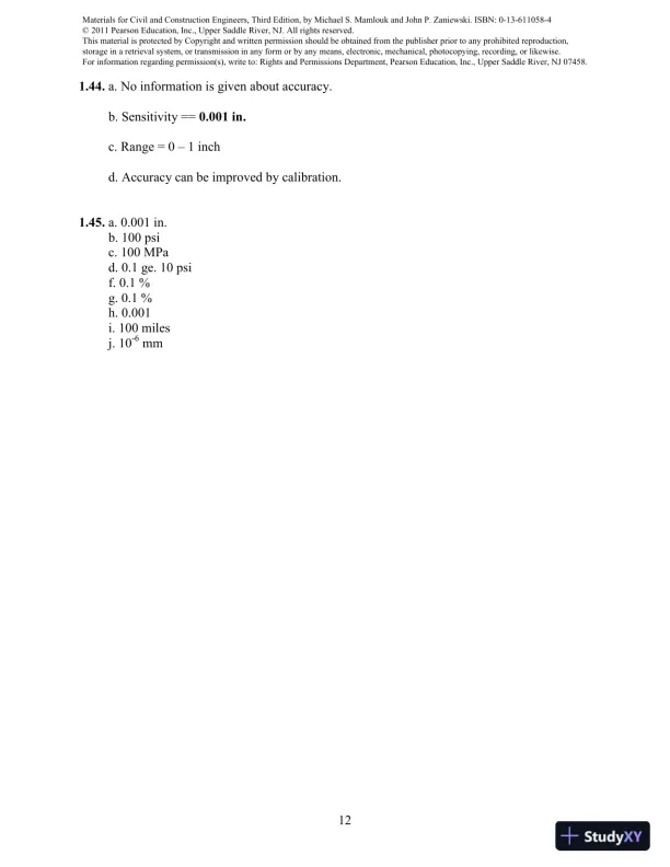
121.44.a. No information is given about accuracy.b. Sensitivity ==0.001 in.c. Range = 01 inchd. Accuracy can be improved by calibration.1.45.a. 0.001 in.b. 100 psic. 100 MPad. 0.1 ge. 10 psif. 0.1 %g. 0.1 %h. 0.001i. 100 milesj. 10-6mm

Page 14

Solution Manual For Materials For Civil And Construction Engineers, 3rd Edition - Page 14 preview image

Loading page image...

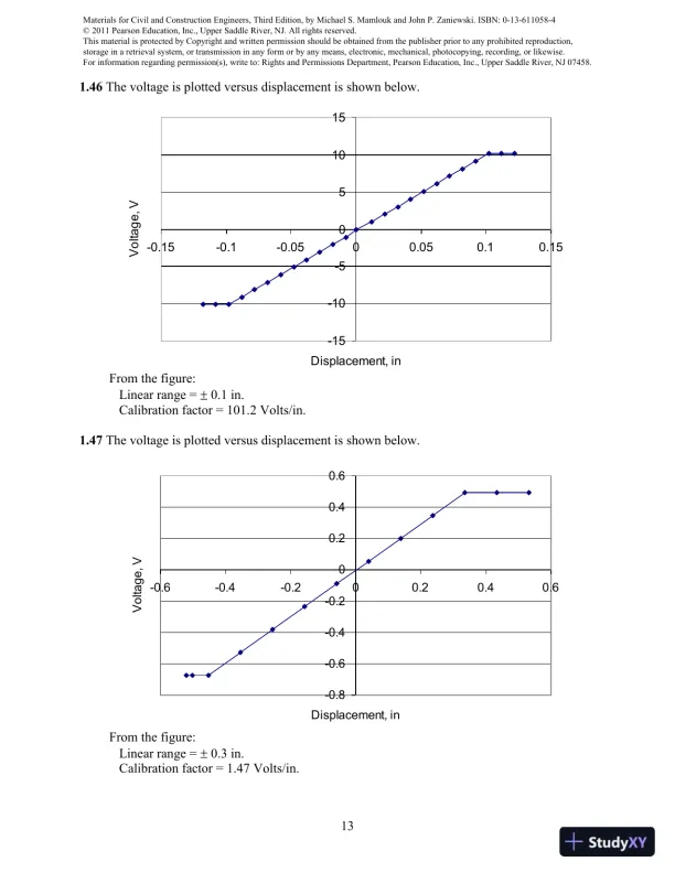
131.46The voltage is plotted versus displacement is shown below.From the figure:Linear range =0.1 in.Calibration factor = 101.2 Volts/in.1.47The voltage is plotted versus displacement is shown below.From the figure:Linear range =0.3 in.Calibration factor = 1.47 Volts/in.-15-10-5051015-0.15-0.1-0.0500.050.10.15Displacement, inVoltage, V-0.8-0.6-0.4-0.200.20.40.6-0.6-0.4-0.200.20.40.6Displacement, inVoltage, V

Page 15

Solution Manual For Materials For Civil And Construction Engineers, 3rd Edition - Page 15 preview image

Loading page image...

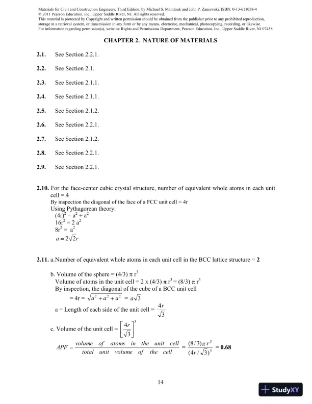
14CHAPTER 2. NATURE OF MATERIALS2.1.See Section 2.2.1.2.2.See Section 2.1.2.3.See Section 2.1.1.2.4.See Section 2.1.1.2.5.See Section 2.1.2.2.6.See Section 2.2.1.2.7.See Section 2.1.2.2.8.See Section 2.2.1.2.9.See Section 2.2.1.2.10.For the face-center cubic crystal structure,number of equivalent whole atoms in each unitcell = 4By inspection the diagonal of the face of a FCC unit cell = 4rUsing Pythagorean theory:(4r)2= a2+ a216r2= 2 a28r2= a2ra222.11.a.Number of equivalent whole atoms in each unit cell in the BCC lattice structure =2b. Volume of the sphere = (4/3)r3Volume of atoms in the unit cell = 2 x (4/3)r3= (8/3)r3By inspection, the diagonal of the cube of a BCC unit cell= 4r =aaa222=a3a = Length of each side of the unit cell=34rc. Volume of the unit cell =334rcelltheofvolumeunittotalcellunittheinatomsofvolumeAPF=33)3/4(.)3/8(rr=0.68

Page 16

Solution Manual For Materials For Civil And Construction Engineers, 3rd Edition - Page 16 preview image

Loading page image...

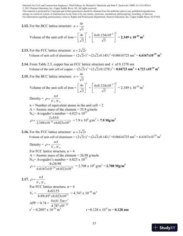
152.12.For the BCC lattice structure:34raVolume of the unit cell of iron =334r=39310124.04xx=2.349 x 10⁻²⁹m32.13.For the FCC lattice structure:ra22Volume of unit cell of aluminum =3)22(r=3)143.022(x=0.06616725 nm3=6.6167x10⁻²⁹m32.14.From Table 2.3, copper has an FCC lattice structure and r of 0.1278 nmVolume of the unit cell of copper =3)22(r=3)1278.022(x=0.04723 nm3= 4.723 x10⁻²⁹m32.15.For the BCC lattice structure:34raVolume of the unit cell of iron =334r=39310124.04xx= 2.349 x 10⁻²⁹m3Density =nAVNCAn = Number of equivalent atoms in the unit cell = 2A = Atomic mass of the element = 55.9 g/moleNA= Avogadro’s number =6.023 x 10232 55 92 349 106 023 102923xxxx...= 7.9 x 10⁶g/m3=7.9 Mg/m32.16.For the FCC lattice structure:ra22Volume of unit cell of aluminum =3)22(r=3)143.022(x=0.06616725 nm3= 6.6167x10⁻²⁹m3Density =nAVNCAFor FCC lattice structure, n = 4A = Atomic mass of the element = 26.98 g/moleNA= Avogadro’s number = 6.023 x 1023232910023.6106167.698.264xxxx= 2.708 x 10⁶g/m3=2.708 Mg/m32.17.NVnAACFor FCC lattice structure, n = 4Vc=23610023.61089.855.634xxxx= 4.747 x 10⁻²⁹m3APF = 0.74 =29310747.4.)3/4(4xrxr3= 0.2097 x 10⁻²⁹m3r =0.128 x 10⁻⁹m =0.128 nm
Preview Mode

This document has 105 pages. Sign in to access the full document!

Study Now!

XY-Copilot AI
Unlimited Access
Secure Payment
Instant Access
24/7 Support
Document Chat

Document Details

Related Documents

View all