Bridge Rectifier and its Analysis: A Study of Output Voltage and Ripple Effects

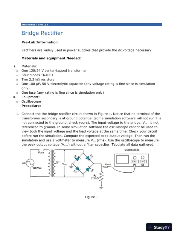
A technical analysis of bridge rectifier functionality, output voltage, and ripple effects.

Christopher Lee
Contributor
4.5
36
2 days ago
Preview (2 of 3)
Sign in to access the full document!
Electronics I and Lab
Bridge Rectifier
Pre-Lab Information
Rectifiers are widely used in power supplies that provide the dc voltage necessary.
Materials and equipment Needed:
i. Materials:
o One 120/24 V center-tapped transformer
o Four diodes 1N4001
o Two 2.2 kΩ resistors
o One 100 μF, 50 V electrolytic capacitor (any voltage rating is fine since is simulation
only)
o One fuse (any rating is fine since is simulation only)
ii. Equipment:
o Oscilloscope
Procedure:
1. Connect the the bridge rectifier circuit shown in Figure 1. Notice that no terminal of the
transformer secondary is at ground potential (some simulation software will not run if is
not connected to the ground, check yours). The input voltage to the bridge, VSEC, is not
referenced to ground. In some simulation software the oscilloscope cannot be used to
view both the input voltage and the load voltage at the same time. Check your circuit
before run the simulation. Compute the expected peak output voltage. Then run the
simulatoin and use a voltmeter to measure VSEC (rms). Use the oscilloscope to measure
the peak output voltage (VLOAD) without a filter capacitor. Tabulate all data gathered.
Figure 1
Preview Mode

Sign in to access the full document!

100%

Study Now!

XY-Copilot AI
Unlimited Access
Secure Payment
Instant Access
24/7 Support
Document Chat

Document Details

Subject
Electrical Engineering & Electronics

Related Documents

View all