Computed and digital radiography notes
Notes on computed and digital radiography: Digital imaging started with CT and MRI. In 1981, Fuji launched the first commercial computed radiography system. CR is a key form of digital radiography.
Alice Edwards
Contributor
4.4
38
3 months ago
Preview (2 of 6)
Sign in to access the full document!
Chapter 15- COMPUTED RADIOGRAPH?
■*“ A cassette, similar to the cassette used in
conventional radiography, encases a phosphor
plate rather than film.
v When x-rays strike the phosphor plate,
electrons are crapped in a high energy state The
latent image is stored in the grains of the
phosphor in the plate.
v The phosphor plate is then fed into a computer
reader where it is scanned by a laser light After
amplification and numbering, the light signal is
digitized through a series of steps, which creates
a visible image.
The patient is positioned the same as in
conventional radiography.
COMPUTED RADIOGRAPHIC' IMAGE RECEPTOR
v Photostimulable Luminescence
> Some materials such as barium fluorohalide
with europium (EaFEriEu or EaFLEu) emit
some light promptly in the way that a
scintillator does following x-ray exposure.
> They also emit light some time later when
exposed to a different light source. Such a
process is called photostimulable
luminescence (FSL).
> The atoms of barium fluorobromide have atomic
numbers of 56, 9, and 35, respectively, with K-
shell electron bindittg energies of 37, 5, and 12
keV, respectively.
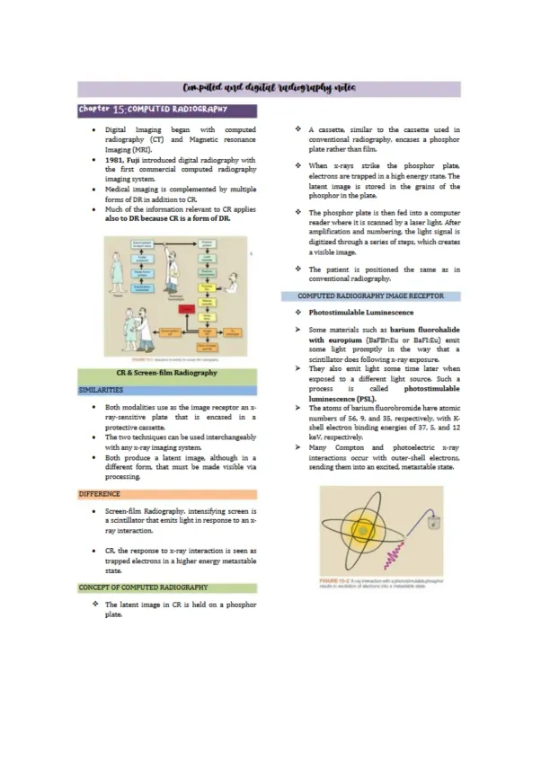
> Many Compton and photoelectric x-ray
interactions occur with outer-shell electrons,
sending them into an excited, metastable state.
Digital Imaging began ivith computed
radiography (CT) and Magnetic resonance
imaging (MRI).
1981, Fuji introduced digital radiography with
the first commercial computed radiography
imaging system
Medical imaging is complemented by multiple
forms of DR in addition to CR.
Much of the informatian relevant to CR applies
also to DR because CRis a form of DR
CR& Screen-film Radiography
SIMILARITIES
■ Both modalities use as the image receptor an x-
ray-serisitive plate that is encased in a
protective cassette.
■ The two techniques can be used interchangeably
with any x-ray imaging system
■ Both produce a latent image, although in a
different form that must be made visible via
processing
DIFFERENCE
Screen-film Radiography, intensifying screen is
a scintillator that emits light in response to an x-
ray interaction.
■ CR, the response to x-ray interaction is seen as
trapped electrons in a higher energy metastable
state.
CONCEPT OF COMPUTED RADIOGRAPHY
The latent image in CR is held on a phosphor
plate.
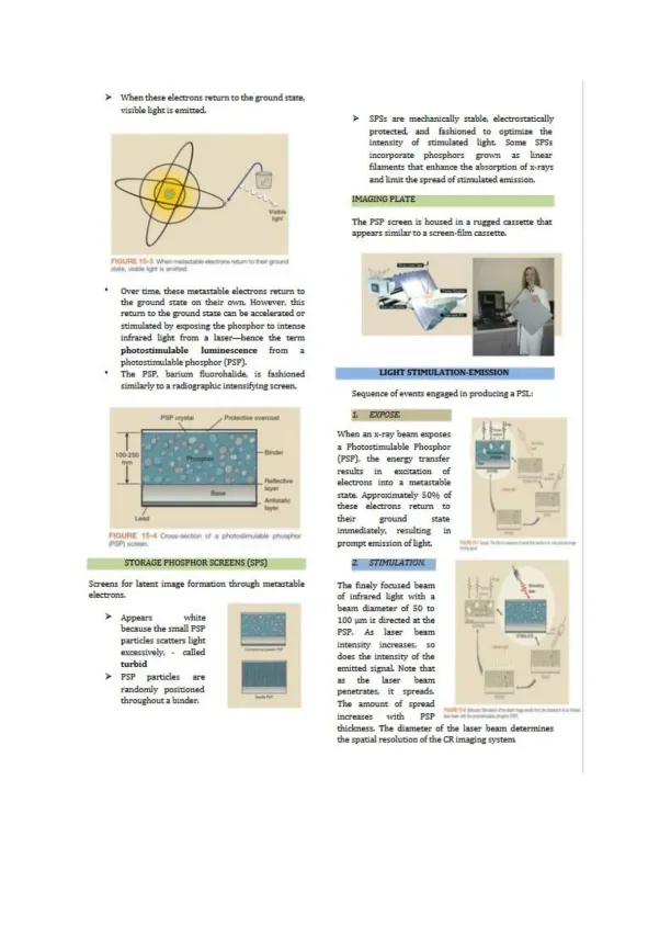
When these electrons return to the ground state.,
visible light is emitted. > SPSs are mechanically stable, electrostatically
protected and fashioned to optimize the
intensity of stimulated light Some SPSs
incorporate phosphors grown as Linear
filaments chat enhance the absorption of x-rays
and limit the spread of stimulated emission,
IMAGING PLATE
The PSP screen is housed in a rugged cassette that
appears similar to a screen-film cassette.
* Over time, these metastable electrons return to
the ground state on their own. However, this
return to the ground state can be accelerated or
stimulated by exposing the phosphor to intense
infrared light from a laser—hence the term
photostimulable luminescence from a
photostimulable phosphor [PSP].
* The PSP. barium fluorohalide, is fashioned
similarly to a radiographic intensifying screen.
LIGHT STIMULATION-EMISSION
Sequence of events engaged in producing a PSL:
1. EXPOSE
When an x-ray beam exposes
a Photostimulable Phosphor
[PSP], the energy transfer
results in excitation of
electrons into a metastable
state. Approximately 50% of
these electrons return to
their ground state
immediately, resulting in
prompt emission of fight
2 STJMEZLA77OM
The finely focused beam
of infrared light with a
beam diameter of 50 to
IDO pm is directed at the
PSP. As laser beam
intensity increases, so
does the intensity of the
emitted signal Note that
as die laser beam
penetrates, it spreads.
The amount of spread
increases with PSP
thickness. The diameter of
the spatial resolution of die (
STORAGE PHOSPHOR SCREENS [STS]
Screens for latent image formation through metastable
electrons.
Appears white
because the small PSP
partides scatters liglit
excessively. - called
turbid
> PSP particles are
randomly positioned
throughout a binder.
e laser beam determines
imaging system
Preview Mode
Sign in to access the full document!
100%
Study Now!
XY-Copilot AI
Unlimited Access
Secure Payment
Instant Access
24/7 Support
Document Chat