Experiment #17 DC Circuits Colin McCormick

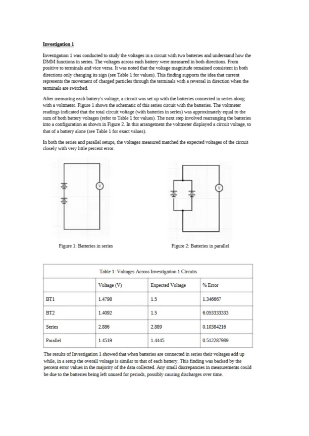
Lab explores DC circuits, measuring voltage, current, and resistance. Verifies Ohm’s Law and Kirchhoff’s Rules using resistors and digital multimeters in series and parallel setups.

Alice Edwards
Contributor
4.2
60
5 months ago
Preview (3 of 9 Pages)
100%
Purchase to unlock

Page 1

Experiment #17 DC Circuits Colin McCormick - Page 1 preview image

Loading page image...

Nor11leasterii Un ivers it yReport for Experiment #17DC CircuitsColin McCormickLab Partner:William Jappe and Diego Salgado GonzalezTA:Harrison AdlerFebruary 20th, 2024

Page 2

Experiment #17 DC Circuits Colin McCormick - Page 2 preview image

Loading page image...

IntroductionIn circuits powered by current, where electrically charged particles flow in a direction specific level ofvoltage, current and resistance are maintained. These values can be impacted by factors such as hew thecircuit components are set up. However certain connections and settings are inherent to circuits withcomponents.The goal of this lab experiment was to observe how changes in resistance, voltage and current manifest ina DC circuit. Factors like the ri'pes of resistors. How they are arranged, along with the tools formeasurements, were considered during the study. Furthermore, the experiment sought to pinpointelements within the circuit that remain constant when its layout is altered.One key aspect of rhe circuit is understanding the relationship between Resistance, Voltage, and Currentof an ohmic component (an electrical component or resistor that has a constant resistance). Thisrelationship is defined by Ohms Law as shown in Equation 1:1: J? £Kirchhoff's Rules are principles that govern rhe flow of currents and voltages within a circuit. These ruleshelp in analj.'zing how voltage and current behave, in sections of a circuit and overall. The first rule,known as the Loop Rule states, that the total sum of voltage changes around a loop in a circuit is zeroindicating that rhe voltages across components equal the supplied witage. Mathematically this can berepresented by Equation 2 where the sum of component voltages subtracted from the supplied voltageequals zero for each resistor in rhe circuit from 1 to n. The rale, called the Junction Rule specifies that atany junction within a circuit the total sum of currents equals zero. This means that all incoming currentsat a junction are distributed among branches or parallel circuits within it. This concept can be expressedby Equation 3 for each resistor from 1 to n, in the circuit.Equation 2: £AV1_q =0Equation 3: Jr I1_n =0In this lab, DC circuits w’ere assembled using a DC power source, resistors with various nominalresistances, and Digital Multimeters (DMMs). The purpose of incorporating DMMs was to accuratelymeasure voltage, current, or resistance at various segments within rhe constructed circuits. Each segmentwith known resistance or witage was checked using a DMM to confirm its actual value. DMMs whereused to measure voltage and current at different parts of the circuit to verify Ohm's Law and KirchhoffsRules. This process ensured the generation of currents and voltages that aligned with the expectations forresistors arranged either in parallel or series, contingent upon the circuit configuration. Additionally, itwas verified that the inclusion of DMMs in the circuits had a negligible impact on their functionalitywhile a steady voltage was maintained.

Page 3

Experiment #17 DC Circuits Colin McCormick - Page 3 preview image

Loading page image...

Investigation 1Investigation 1 was conducted to study the voltages in a circuit with two batteriesandunderstand how theDMMfunctions in series. The voltages across each battery were measured in both directions. Frompositive to terminals and vice versa. It was noted that the voltage magnitude remained consistent in bothdirections only changing its sign (see Table 1 for values). This finding supports the idea that currentrepresents the movement of charged particles through the terminals with a reversal in direction when theterminals are switched.After measuring each battery's voltage, a circuit was set up with the batteries connected in series alongwith a voltmeter. Figure 1 shows the schematic of this series circuit with the batteries. The voltmeterreadings indicated that the total circuit voltage (with batteries in series) was approximately equal to thesumofboth battery voltages (refer to Table1 forvalues). The next step involved rearranging the batteriesinto a configuration as shown in Figure 2. In this arrangement the voltmeter displayed a circuit voltage, tothat of a batten7alone (see Table 1 for exact values).In both the series and parallel setups, the voltages measured marched the expected voltages of the circuitclosely with very little percent error.Figure 1: Batteries in seriesFigure 2: Batteries in parallelTable 1: Voltages Across Investigation 1 CircuitsVoltage (V)Expected Voltage% ErrorBT11.47981.51 346667BT21.40921.56.053333333Series2.8862.8890.10384216Parallel1.45191.44450.512287909The results of Investigation 1 showed that wphen batteries are connected in series their ’s’oltages add upwhile, in a setup the overall voltage is similar to that of each batten;. This finding was backed by thepercent error values in the majority of the data collected. Any small discrepancies in measurements couldbe due to the batteries being left unused for periods, possibly causing discharges over time.
Preview Mode

This document has 9 pages. Sign in to access the full document!

Study Now!

XY-Copilot AI
Unlimited Access
Secure Payment
Instant Access
24/7 Support
Document Chat

Related Documents

View all