Solution Manual For Principles of Instrumental Analysis, 7th Edition

Get the textbook answers you need with Solution Manual For Principles of Instrumental Analysis, 7th Edition, an essential guide to solving textbook problems.

Isabella White
Contributor
4.8
40
5 months ago
Preview (16 of 260 Pages)
100%
Purchase to unlock

Page 1

Solution Manual For Principles of Instrumental Analysis, 7th Edition - Page 1 preview image

Loading page image...

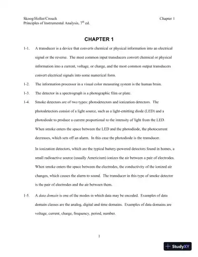
Skoog/Holler/CrouchChapter 1Principles of Instrumental Analysis, 7thed.1CHAPTER 11-1.A transducer is a device that converts chemical or physical information into an electricalsignal or the reverse. The most common input transducers convert chemical or physicalinformation into a current, voltage, or charge, and the most common output transducersconvert electrical signals into some numerical form.1-2.The information processor in a visual color measuring system is the human brain.1-3.The detector in a spectrograph is a photographic film or plate.1-4.Smoke detectors are of two types: photodetectors and ionization detectors. Thephotodetectors consist of a light source, such as a light-emitting diode (LED) and aphotodiode to produce a current proportional to the intensity of light from the LED.When smoke enters the space between the LED and the photodiode, the photocurrentdecreases, which sets off an alarm. In this case the photodiode is the transducer.In ionization detectors, which are the typical battery-powered detectors found in homes, asmall radioactive source (usually Americium) ionizes the air between a pair of electrodes.When smoke enters the space between the electrodes, the conductivity of the ionized airchanges, which causes the alarm to sound. The transducer in this type of smoke detectoris the pair of electrodes and the air between them.1-5.Adata domainis one of the modes in which data may be encoded. Examples of datadomain classes are the analog, digital and time domains. Examples of data domains arevoltage, current, charge, frequency, period, number.

Page 2

Solution Manual For Principles of Instrumental Analysis, 7th Edition - Page 2 preview image

Loading page image...

Page 3

Solution Manual For Principles of Instrumental Analysis, 7th Edition - Page 3 preview image

Loading page image...

Principles of Instrumental Analysis, 7thed.Chapter 121-6.Time-domain signals include period, frequency, and pulse width. The information isencoded in the time relationship of signal fluctuations.1-7.Input TransducerUsePhototubeConvert light intensity to ananalog currentGlass electrodeConvert electrode potential to avoltage related to pHElectron multiplierConvert ion intensity to acorresponding electric currentThermal conductivityConverts sample thermalconductivity to related voltage1-8.A figure of merit is a number that provides quantitative information about someperformance criterion for an instrument or method.1-9.Letcs= molar concentration of Cu2+in standard = 0.0275 Mcx= unknown Cu2+concentrationVs= volume of standard = 0.500 mLVx= volume of unknown = 25.0 mLS1= signal for unknown = 25.2S2= signal for unknown plus standard = 45.1Assuming the signal is proportional tocxandcs, we can writeS1=KcxorK=S1/cxAfter adding the standard2xxssxsV cV cSKVV+=+Substituting forKand rearranging gives,

Page 4

Solution Manual For Principles of Instrumental Analysis, 7th Edition - Page 4 preview image

Loading page image...

Principles of Instrumental Analysis, 7thed.Chapter 13121()ssxxsxS V ccSVVS V=+cx425.20.500 mL0.0275 M= 6.6610M45.1(0.500 mL + 25.0 mL)(25.225.0 mL)××=××1-10. The results are shown in the spreadsheet below.(a)Slope,m= 0.0701, intercept,b= 0.0083(b)From LINEST results, SD slope,sm= 0.0007, SD intercept,sb= 0.0040(c)95% CI for slopemism±tsmFor 95% probability andN –2 = 4 degrees of freedom,t= 2.78. 95% CI form= 0.0701±2.78×0.0007 = 0.0701±0.0019 or 0.070±0.002For intercept, 95% CI =b±tsb= 0.0083±2.78×0.004 = 0.0083±0.011 or 0.08±0.01(d)cu= 4.87±0.086 mM or 4.87±0.09 mM

Page 5

Solution Manual For Principles of Instrumental Analysis, 7th Edition - Page 5 preview image

Loading page image...

Principles of Instrumental Analysis, 7thed.Chapter 141-11.The spreadsheet below gives the results(a)See plot in spreadsheet.(b)cu= 0.410μg/mL(c)S= 3.16Vs+ 3.25(d)13.2462.000μg/mL0.410μg/mL3.164 mL5.00 mLsuubccmV×===×(e)From the spreadsheetsc= 0.002496 or 0.002μg/mL

Page 6

Solution Manual For Principles of Instrumental Analysis, 7th Edition - Page 6 preview image

Loading page image...

Skoog/Holler/CrouchChapter 2Principles of Instrumental Analysis, 7th ed.1CHAPTER 22-1.(a) Applying the voltage divider equation (2-10)11231.0 =10++RRRR21234.0 =10++RRRRV3= 10.0V – 1.0 V – 4.0 V = 5.0 V31235.0 =10++RRRRDividing the first equation by the second, givesR1/R2= 1.0/4.0Similarly,R2/R3= 4.0/5.0LettingR1= 250Ω,R2= 250×4.0 = 1.0 kΩ,andR3= 1.0 kΩ×5.0/4.0 = 1.25 kΩ. Use a 1.0 kΩresistor and a 250 kΩresistor inseries. The 500 kΩresistor is not used.(b)V3=IR3= 10.0 V – 1.0 V – 4.0 V = 5.0 V(c)I=V/(R1+R2+R3) = 10.0 V/(250Ω+ 1000Ω+ 1250Ω) = 0.004 A (4.0 mA)(d)P=IV= 0.004 A×10.0 V = 0.04 W(Equation 2-2)2-2.(a) From Equation 2-10,V2= 15×400/(200 + 400 + 2000) = 2.31 V(b)P=22V/R2= (2.31)2/400 = 0.013 W(c) TotalP=V2/Rs= (15)2/2600 = 0.087 W

Page 7

Solution Manual For Principles of Instrumental Analysis, 7th Edition - Page 7 preview image

Loading page image...

Principles of Instrumental Analysis, 7thed.Chapter 22Percentage loss inR2= (0.013/0.087)×100 = 15%2-3.V2,4= 24.0×[(2.0 + 4.0)×103]/[(1.0 + 2.0 + 4.0)×103] = 20.6 VWith the meter in parallel across contacts 2 and 4,2,4+ 6.0 k111=+=(2.0 + 4.0) k6.0 kMMMRRRRΩΩ×ΩR2,4= (RM×6.0 kΩ)/(RM+ 6.0 kΩ)(a)R2,4= (4.0 kΩ×6.0 kΩ)/(4.0kΩ+ 6.0kΩ) = 2.40kΩVM= (24.0 V×2.40 kΩ)/(1.00kΩ+ 2.40kΩ) = 16.9Vrel error =16.9 V20.6 V100% =18%20.6 V×Proceeding in the same way, we obtain (b) –1.2% and (c) –0.2%2-4.Applying Equation 2-19, we can write(a)10001.0% =100%(1000)MRΩ×ΩRM= (1000×100 – 1000)Ω= 99000Ωor 99 kΩ(b)10000.1% =100%(1000)MRΩ×ΩRM= 999 kΩ2-5.ResistorsR2andR3are in parallel, the parallel combinationRpis given by Equation 2-17Rp= (500×250)/(500 + 250) = 166.67Ω(a) This 166.67ΩRpis in series withR1andR4. Thus, the voltage acrossR1isV1= (15.0×250)/(250 + 166.67 + 1000) = 2.65 V

Page 8

Solution Manual For Principles of Instrumental Analysis, 7th Edition - Page 8 preview image

Loading page image...

Principles of Instrumental Analysis, 7thed.Chapter 23V2=V3= 15.0 V×166.67/1416.67 = 1.76 VV4= 15.0 V×1000/1416.67 = 10.59 V(b)I1R1=V1= 2.647 VI1= 2.647/250 = 0.01059A (1.06×10⁻²A)I2= 1.76 V/500Ω= 3.5×10⁻³AI3= 1.76 V /250Ω= 7.0×10⁻³AI4= 10.59 V/ 1000Ω= 0.01059Α(1.06×10⁻²A)(c)P=IV= 1.76 V×7.0×10–3A = 1.2×10⁻²W(d)Since point 3 is at the same potential as point 2, the voltage between points 3 and4 (V)is the sum of the drops across the 166.67Ωand the 1000Ωresistors. Or,V= 1.76 V + 10.59 V = 12.35 V. It is also the source voltage minus theV1V= 15.0 – 2.65 = 12.35 V2-6.The resistance between points 1 and 2 is the parallel combination orRBandRCR1,2= 3.0 kΩ×4.0 kΩ/(3.0 kΩ+ 4.0 kΩ) = 1.71 kΩSimilarly the resistance between points 2 and 3 isR2,3= 2.0 kΩ×1.0 kΩ/(2.0 kΩ+ 1.0 kΩ) = 0.667 kΩThese two resistors are in series withRAfor a total series resistanceRTofRT= 1.71 kΩ+ 0.667 kΩ+ 2.0 kΩ= 4.38 kΩI= 24/(4380Ω) = 5.5×10⁻³A(a)P1,2=I2R1,2= (5.5×10⁻³)2×1.71×103= 0.052 W(b) As aboveI= 5.5×10⁻³A (5.5 mA)(c)VA=IRA= 5.5×10–3A×2.0×103Ω= 11.0 V

Page 9

Solution Manual For Principles of Instrumental Analysis, 7th Edition - Page 9 preview image

Loading page image...

Principles of Instrumental Analysis, 7thed.Chapter 24(d)VD= 24×R2,3/RT= 24×0.667/4.38 = 3.65 V(e)V5,4= 24 –VA= 24 – 11.0 = 13 V2-7.With the standard cell in the circuit,Vstd=Vb×AC/ABwhereVbis the battery voltage1.018 =Vb×84.3/ABWith the unknown voltageVxin the circuit,Vx=Vb×44.2/ABDividing the third equation by the second gives,1.018 V84.3 cm= 44.3 cmxVVx= 1.018×44.3 cm/84.3 cm = 0.535 V2-8.=100%SrMSRERR×+ForRS= 20ΩandRM= 10Ω,20=100% =67%1020rE×+Similarly, forRM= 50Ω,20=100% =29%5020rE×+The other values are shown in a similar manner.2-9.Equation 2-20 isstdstd=100%rLRERR×+ForRstd= 1ΩandRL= 1Ω,1=100% =50%11rEΩ×Ω+Ω

Page 10

Solution Manual For Principles of Instrumental Analysis, 7th Edition - Page 10 preview image

Loading page image...

Principles of Instrumental Analysis, 7thed.Chapter 25Similarly forRL= 10Ω,1=100% =9.1%101rEΩ×Ω+ΩThe other values are shown in a similar manner.2-10.(a)Rs=V/I= 1.00 V/20×10–6A = 50000Ωor 50 kΩ(b) Using Equation 2-1950 k1% =100%50 kMRΩ×+ΩRM= 50 kΩ×100 – 50 kΩ= 4950 kΩor5 MΩ211.Ι1= 90/(25 + 5000) = 1.791×10⁻²AI2= 90/(45 + 5000) = 1.784×10⁻²A% change = [(1.784×10⁻²A – 1.791×10⁻²A)/ 1.791×10⁻²A]×100% = – 0.4%2-12.I1= 12.5/420 = 2.976×10⁻²AI2= 12.5/440 = 2.841×10⁻²A% change = [(2.841×10⁻²– 2.976×10⁻²)/ 2.976×10–2]×100% = –4.5%2-13.i=Iinitet/RC(Equation 2-35)RC= 25×106Ω×0.2×10–6F = 5.00 sIinit= 24V/(25×106Ω)= 9.6×10⁻⁷Ai= 9.6×10⁻⁷et/5.00A or 0.96×e–t/5.0μAt, si,μAt, si,μA0.000.961.00.7860.0100.958100.1300.100.941

Page 11

Solution Manual For Principles of Instrumental Analysis, 7th Edition - Page 11 preview image

Loading page image...

Principles of Instrumental Analysis, 7thed.Chapter 262-14.vC=VCe–t/RC(Equation 2-40)vC/VC= 1.00/100 for discharge to 1%0.0100 =e–t/RC=6/(0.02510)tRe××ln 0.0100 = –4.61 = –t/(2.5×10–8R)t= 4.61×2.5×10–8R= 1.15×10⁻⁷R(a) WhenR= 10 MΩor 10×106Ω,t= 1.15 s(b) Similarly, whenR= 1 MΩ,t= 0.115 s(c) WhenR= 1 kΩ,t= 1.15×10⁻⁴s2-15.(a) WhenR= 10 MΩ,RC= 10×106Ω×0.025×10–6F = 0.25 s(b)RC= 1×106×0.025×10–6= 0.025 s(c)RC= 1×103×0.025×10–6= 2.5×10⁻⁵s2-16.Parts (a) and (b) are given in the spreadsheet below. For part (c), we calculate thequantities fromi=Iinite-t/RC,vR=iR, andvC= 25 –vRFor part (d) we calculate the quantities from/=tRCCvieR,vR=iR, andvC= –vRThe results are given in the spreadsheet.

Page 12

Solution Manual For Principles of Instrumental Analysis, 7th Edition - Page 12 preview image

Loading page image...

Principles of Instrumental Analysis, 7thed.Chapter 272-17.Proceeding as in Problem 2-16, the results are in the spreadsheet

Page 13

Solution Manual For Principles of Instrumental Analysis, 7th Edition - Page 13 preview image

Loading page image...

Principles of Instrumental Analysis, 7thed.Chapter 28

Page 14

Solution Manual For Principles of Instrumental Analysis, 7th Edition - Page 14 preview image

Loading page image...

Principles of Instrumental Analysis, 7thed.Chapter 292-18.In the spreadsheet we calculateXC,Z, andφfromXC= 2/2πfC,22=+CZRX, andφ= arc tan(XC/R)2-19.Let us rewrite Equation 2-54 in the formo2()1==()(2π)1ppiVyVfRC+y2(2πfRC)2+y2= 12221111=1 =2πRC2πRCyfyyThe spreadsheet follows

Page 15

Solution Manual For Principles of Instrumental Analysis, 7th Edition - Page 15 preview image

Loading page image...

Principles of Instrumental Analysis, 7thed.Chapter 2102-20.By dividing the numerator and denominator of the right side of Equation 2-53 byR, weobtaino2()1==()1 + (1/ 2π)ppiVyVfRCSquaring this equation yieldsy2+y2/(2πfRC)2= 1222π=1yfRCy221= 2π1yfRCyThe results are shown in the spreadsheet that follows.

Page 16

Solution Manual For Principles of Instrumental Analysis, 7th Edition - Page 16 preview image

Loading page image...

Principles of Instrumental Analysis, 7thed.Chapter 211
Preview Mode

This document has 260 pages. Sign in to access the full document!

Study Now!

XY-Copilot AI
Unlimited Access
Secure Payment
Instant Access
24/7 Support
Document Chat

Document Details

Related Documents

View all