Solution Manual for Electronics for Electricians, 7th Edition

Solution Manual for Electronics for Electricians, 7th Edition simplifies complex textbook exercises with easy-to-understand solutions and step-by-step guides.

Michael Davis
Contributor
4.4
53
4 months ago
Preview (16 of 58)
Sign in to access the full document!
Electronics for Electricians, Seventh Edition 1
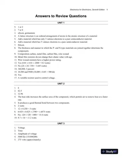
Answers to Review Questions
UNIT 1
5. 1 or 2
2. 7 or 8
3. silicon, germanium
4. A lattice structure is an ordered arrangement of atoms in the atomic structure of a material.
5. Add a material which has only 3 valence electrons to a pure semiconductor material.
6. Add a material which has 5 valence electrons to a pure semiconductor material.
7. Silicon
8. The thickness and manner in which the P- and N-type materials are joined together determine the
components.
9. Composition carbon, metal film, carbon film, wire wound
10. Metal film resistors do not change their ohmic value with age.
11. Wire wound resistors have a higher power rating.
12. Yes (0.01 × 0.01 × 2000 = 0.2 watts)
13. No (24 × 24 / 350 = 1.645 watts)
14. 360,000, 5 percent
15. 10,500 and 9500 (10,000 × 0.05 = 500 Ω)
16. Yes
17. A variable resistor used to control voltage.
UNIT 2
1. 6
2. 62.5
3. 12.96
4. The heat sink increases the surface area of the component, which permits air to remove heat at a faster
rate.
5. It produces a good thermal bond between two components.
6. 2 watts
7. 12 × 0.250 = 3 watts
8. 0.025 × 0.025 × 2700 = 1.6875 watts
9. No. 120 × 120 / 1000 = 14.4 watts
10. 0.7 × 16 = 11.2 watts
UNIT 3
1. Voltage
2. Time
3. Amplitude of voltage
4. 5000 Hz (1/0.000200)
5. 275 volts (approximately)
2 Electronics for Electricians, Seventh Edition
6. 30 volts peak, 6250 Hz
7. To show the position of the trace if it is off the display
8. The alternate mode alternates sweeps between channel 1 and channel 2. The cop mode alternates the
sweep between the two channels several times during one sweep.
9. It will burn a spot on the face of the CRT.
10. It permits the oscilloscope to trigger on the positive or negative half of the waveform.
11. 5 MΩ (20,000 × 250)
12. 9600 Ω (20,000 × 12 = 240,000 Ω) (1/10,000 + 1/240,000 = 1/0.000104167)
13. Digital ohmmeter
14. 2.09 mA (4.6/2200)
15. Digital voltmeter
UNIT 4
1. 2
2. Silicon and germanium
3. 0.6 to 0.7
4. Positive
5. The amount of voltage it can hold off in the reverse direction.
6. The diode should show continuity through it when the positive lead of the ohmmeter is connected to the
anode but not to the cathode.
UNIT 5
1. Light-emitting diode
2. DC
3. 1.7 volts
4. Light being emitted by the device
5. 2000 Ω
6. 0.45 volts
7. Arrows point away from the device when the symbol represents an LED. Arrows point toward the
device when the symbol represents a photodiode.
8. The photodiode can operate at a greater speed.
9. In darkness
10. The light would be turned on during the daylight hours and off at night.
UNIT 6
1. A device that changes AC voltage into DC voltage.
2. The half-wave rectifier
3. The two-diode type of rectifier
4. The bridge rectifier
5. 8.1 volts (18/2 = 9, 9 × 0.9 = 8.1)
6. The two-diode type

Loading page 6...

Loading page 7...

Loading page 8...

Loading page 9...

Loading page 10...

Loading page 11...

Loading page 12...

Loading page 13...

Loading page 14...

Loading page 15...

Loading page 16...

13 more pages available. Scroll down to load them.

Preview Mode

Sign in to access the full document!

100%

Study Now!

XY-Copilot AI
Unlimited Access
Secure Payment
Instant Access
24/7 Support
Document Chat

Related Documents

View all